The Large Zenith Telescope
Picture Gallery
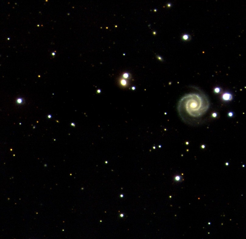
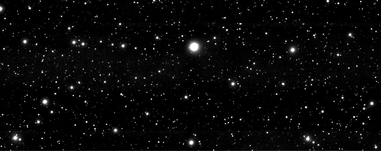
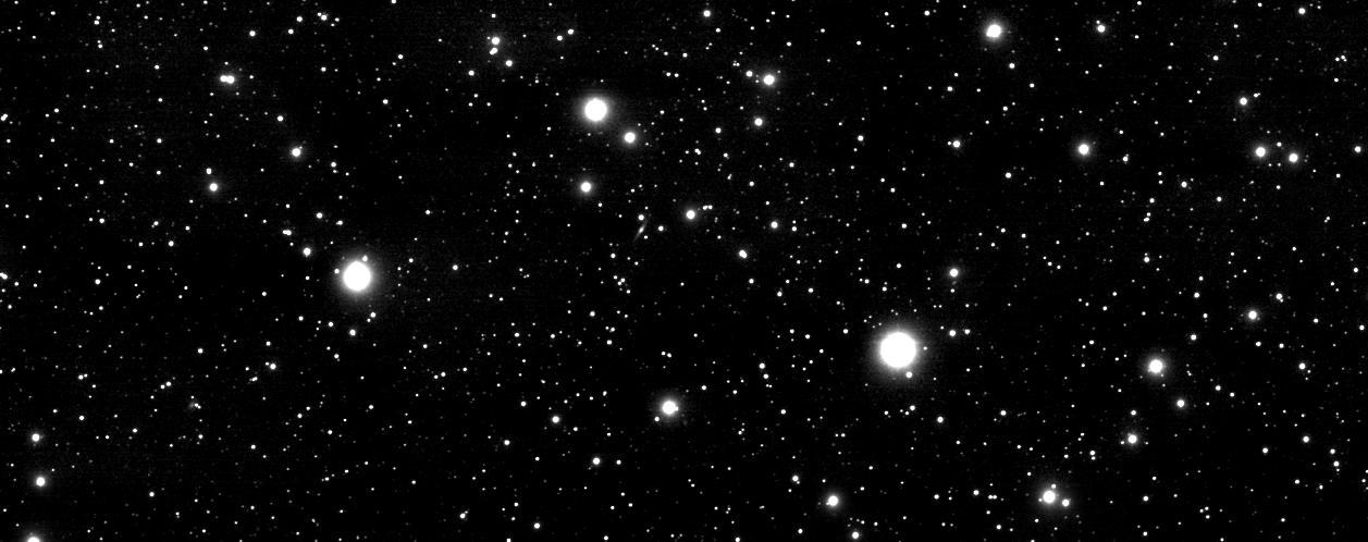
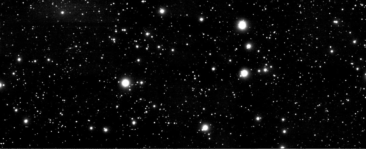
Recent Images from the Telescope
|
|
|
|
The Observatory
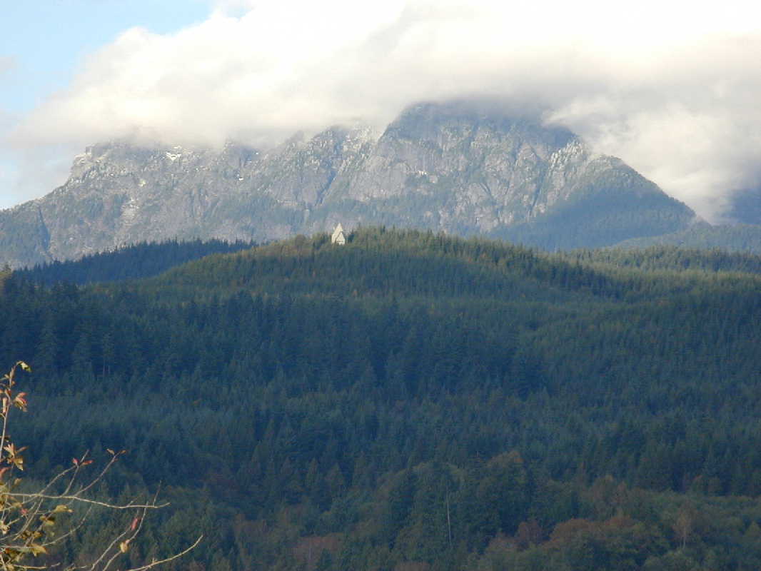 |
The LZT is located at the Liquid Mirror Observatory in the UBC Malcolm Knapp Research Forest in Maple Ridge, British Columbia. |
Telescope Construction
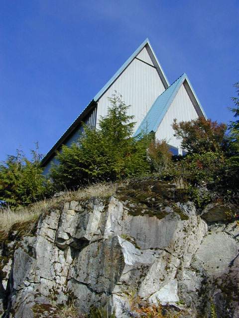 |
This view of the observatory reveals the granitic rock upon which it is built. It is located atop a hill which rises 400 metres above the Fraser Valley. The roof, which is steeply pitched to shed snow, rolls back on steel tracks to expose the telescope. The observatory site offers spectacular views and can be reached by a 45 minute walk from the Research Forest gate. When the telescope begins operation, astronomical images will be posted on this web site. |
 |
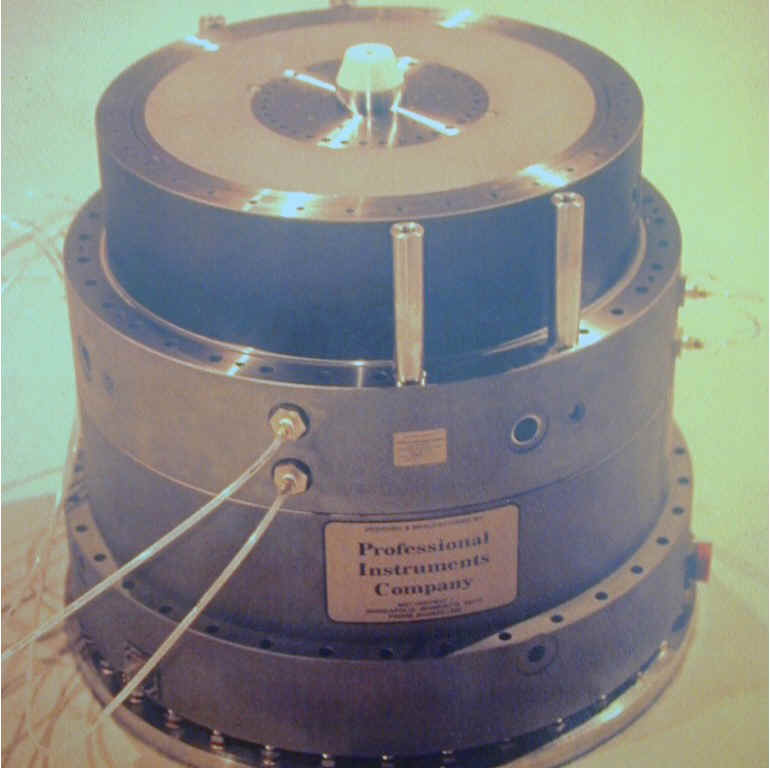 |
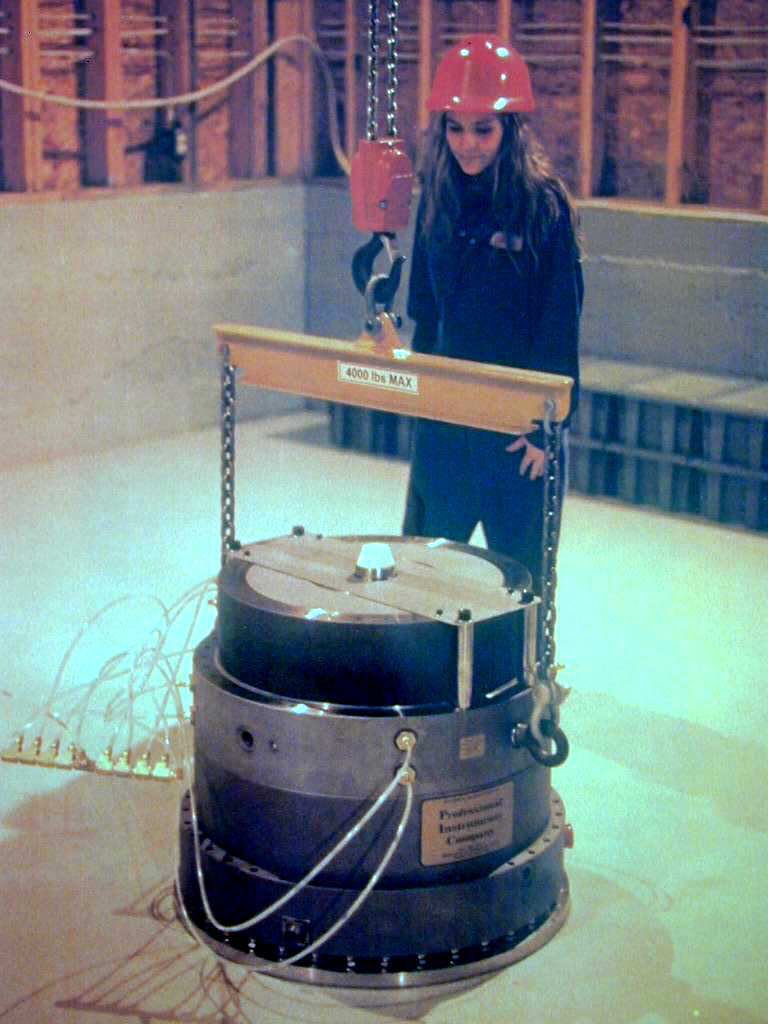
| Lifting the air bearing into place by means of a 2-tonne overhead crane, installed in the peak of the roof. The concrete floor is over a metre thick. | The air bearing on its support plate. Loads are transfered to the concrete floor by 36 spherical balls set in screws in the stainless steel ring which is grouted to the floor. |
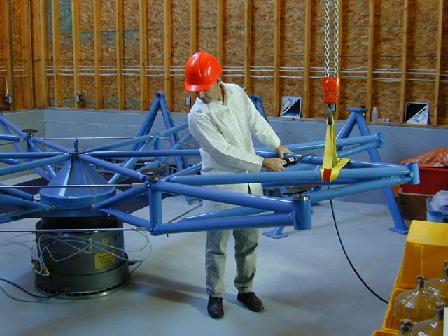 |
| Assembling the primary mirror support system. The mirror is supported by six primary trusses, seen here attached to the hub, and six secondary trusses. Here, the first of the secondary trusses is being positioned. The mirror shell is supported at 19 points, on the black aluminum disks, three of which are shown in the picture. |
 |
 |
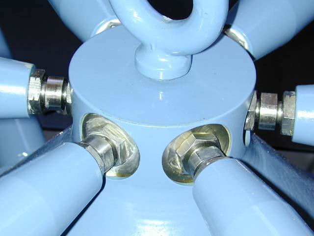
| Close up of the central hub and radial arms. Turnbuckle screws allow adjustment of the lengths. | Attachment point of a primary truss to the hub. The air bearing can be seen below. |
 |
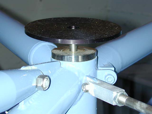 |
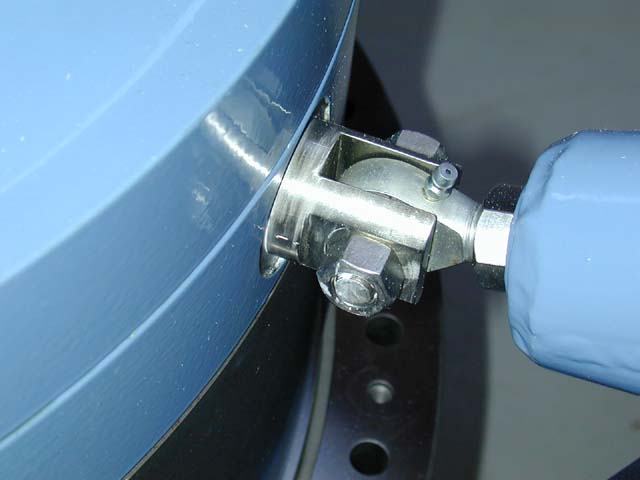
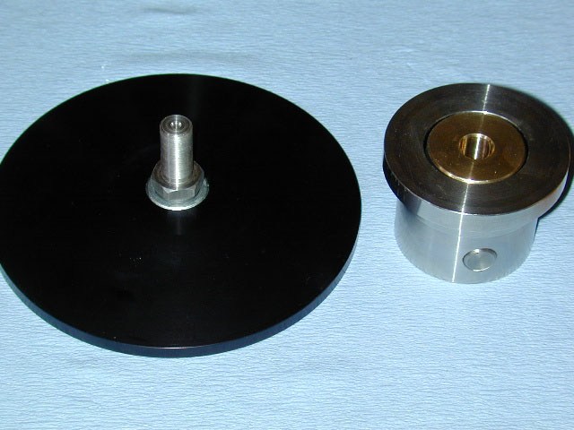
| One of the mirror axial supports. A fine-pitched screw provides height adjustment. Self-aligning bearings and a pivot allow the support to adapt to differences in thermal expansion of the truss and mirror shell. | An axial support in place in the mirror truss. The screw allows the mirror surface (which supports the thin mercury layer) to be adjusted to within a few microns. |
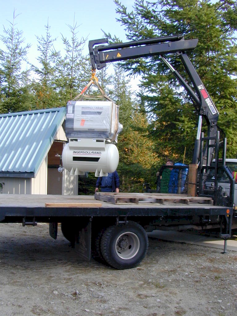 |
This view shows the new air
compressor being unloaded at the telescope site.
The air bearing requires a constant supply of air to create the air cushion which supports the rotating liquid mirror. We have recently replaced the small reciprocating compressor, used for the 2.7 meter LMT tests, with a heavy-duty rotary-screw compressor. Air from this compressor is filtered and dehumidified and then passes through an underground pipe to the main building. There it is filtered further and piped to the bearing. |
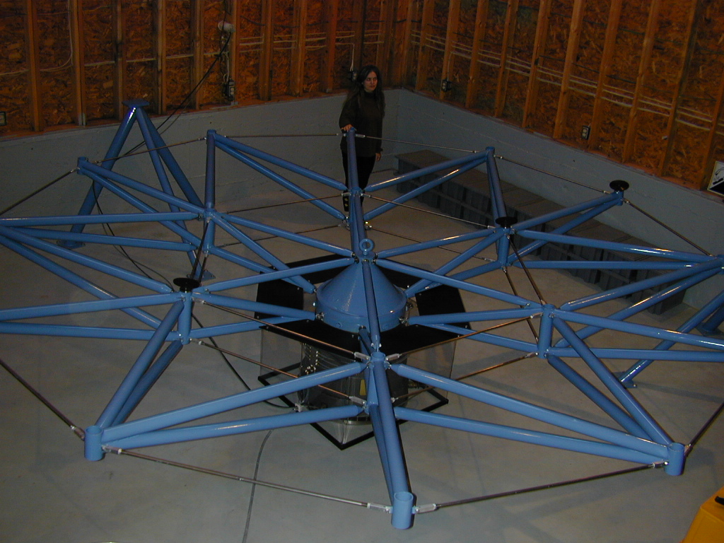 |
This picture shows the assembled primary mirror support system. |
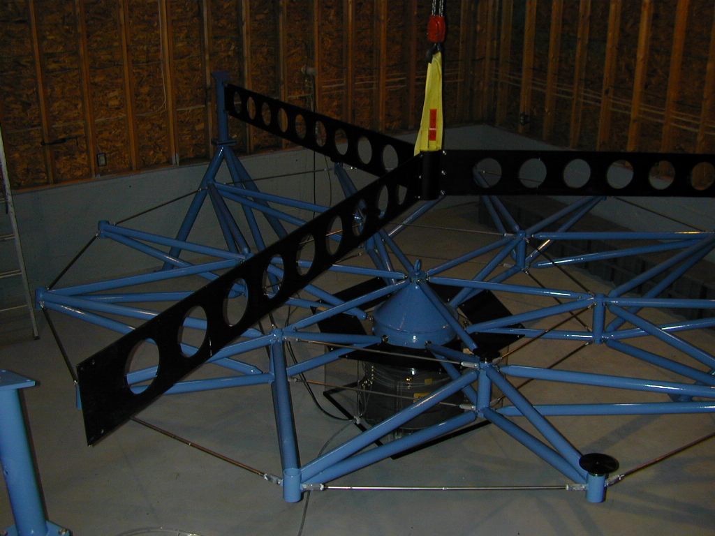 |
The tertiary mirror spider is being installed in this picture. The spider supports a future tertiary mirror that will feed light from the telescope to stationary instruments mounted on an optical table located in the instrument room. The spider also acts as a brace for the hexapod support posts. |
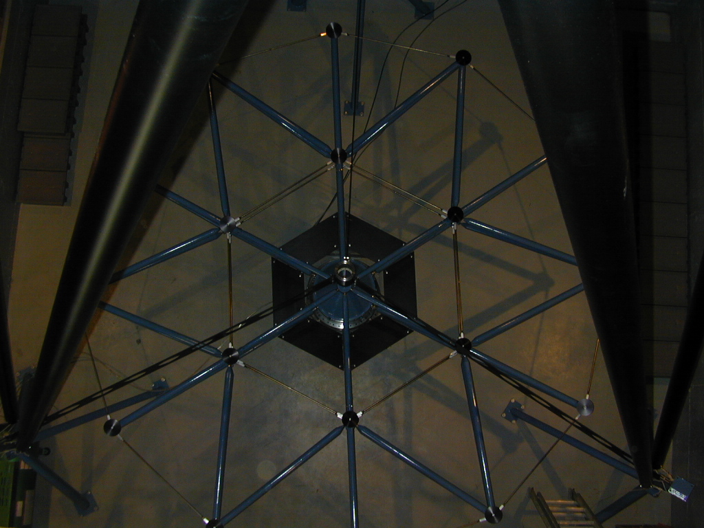 |
This shows the view looking down from the prime-focus access platform mounted in the roof. One sees the primary mirror support system and the tertiary spider. Two hexapod legs are visible at the sides of the image. |
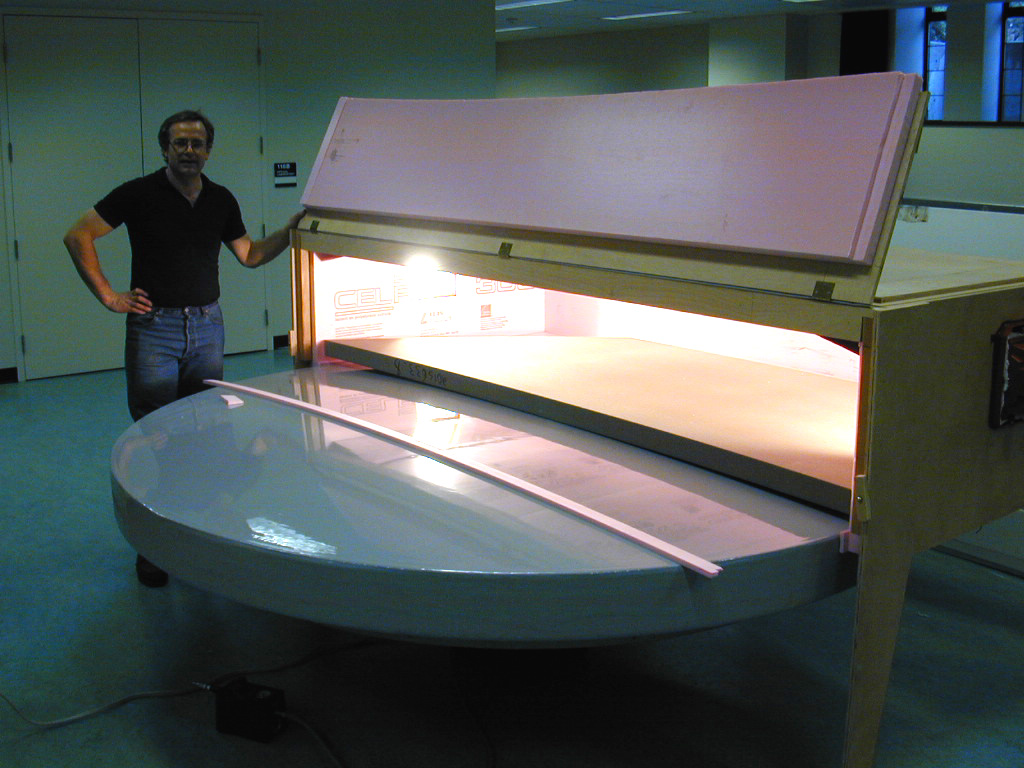 |
The first of the core segments being readied for thermoforming in the oven. After heating, the foam core material curves to the 18-metre of the mold. Two pieces are then jointed to form the core of a single hexagonal primary mirror segment. |
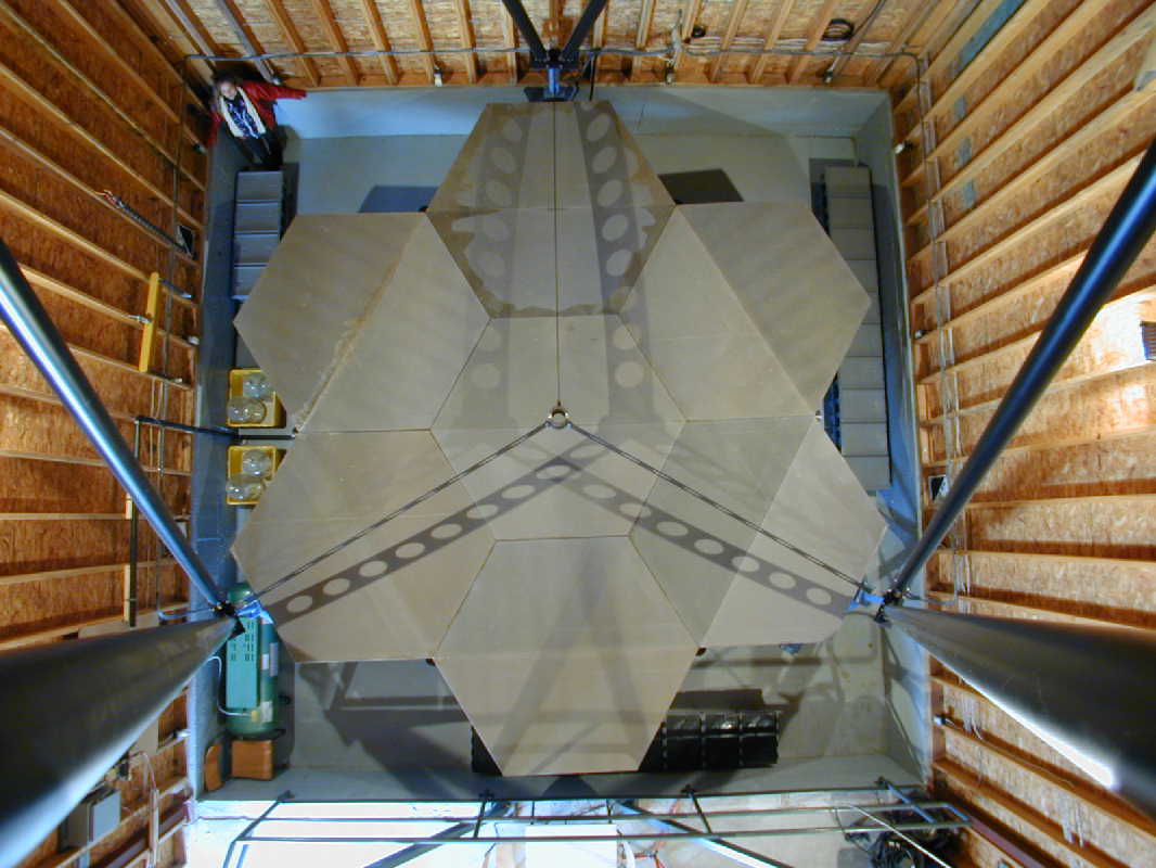 |
View from the top of the telescope showing the seven main hexagonal segments that form the surface of the primary mirror. Six smaller triangular sections, cut from two additional hexagons, will compete the circle. |
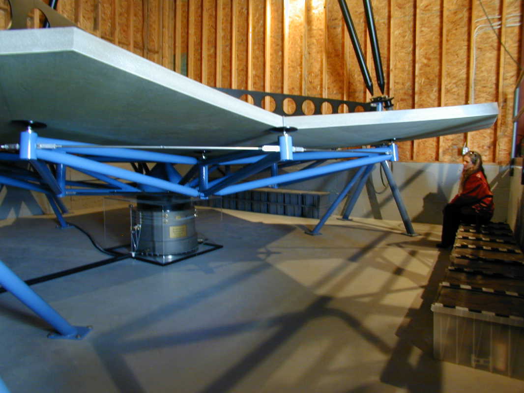 |
Side view of the primary mirror during installation of the segments. The supporting structure and air bearing can be seen. |
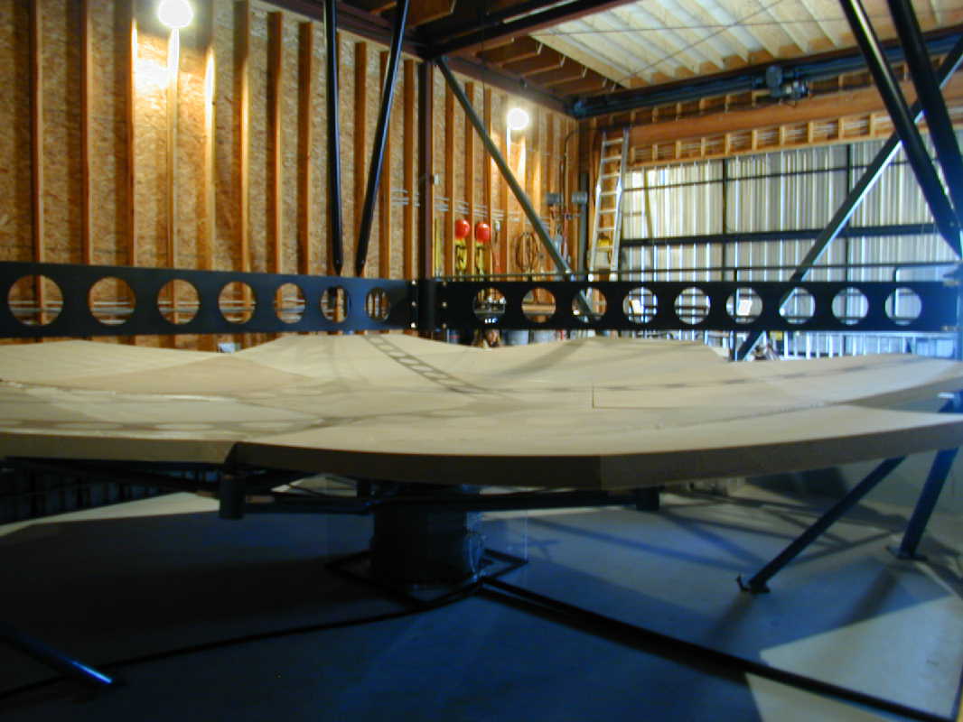 |
Side view of the primary mirror surface during segment installation. |
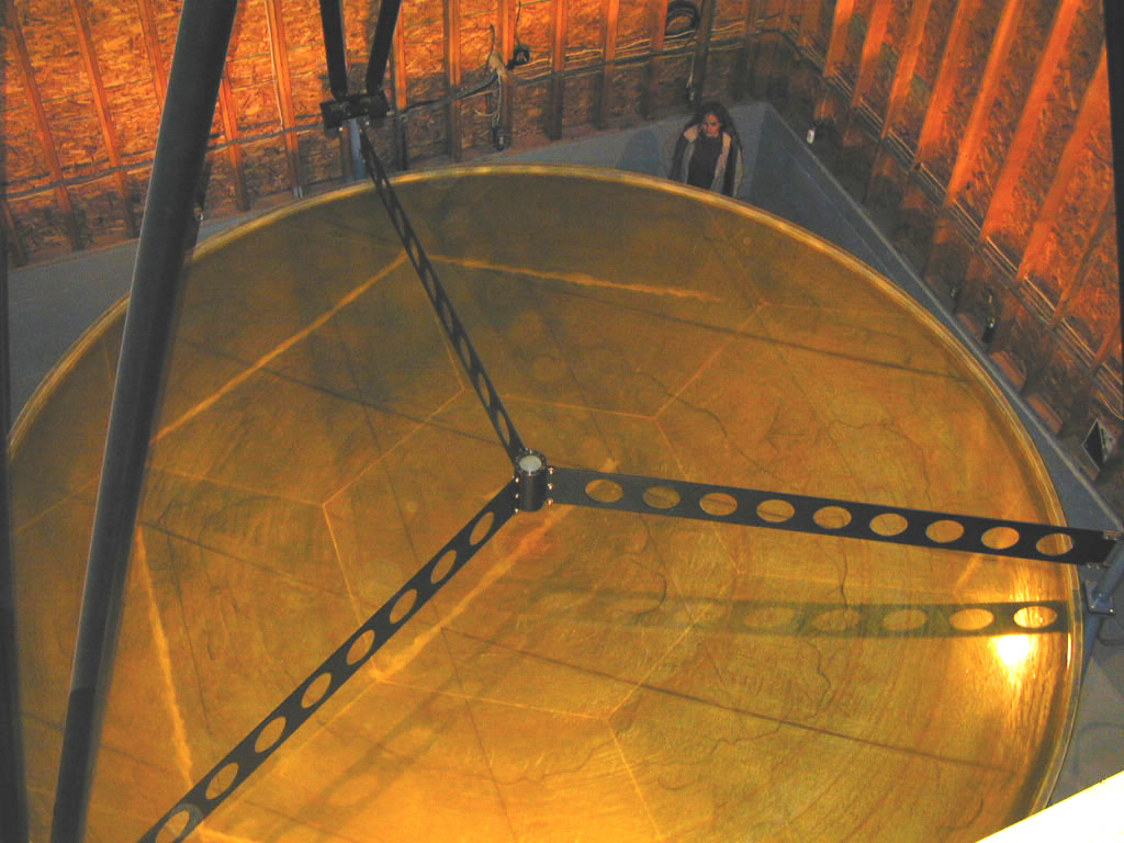 |
The completed primary mirror following spincasting. |
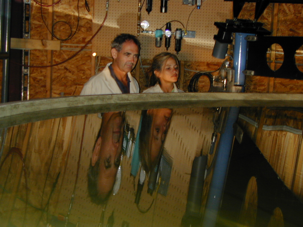 |
View of the primary mirror undergoing initial tests using water. |
Links